My early challenges with recycle units in process simulations
My first encounter with process simulations was 20 years ago during a summer job. I was given the task to implement a model of a gas-compression train of an oil field in a commercial process simulation software. Everything went well until I encountered a stream going backwards in the process, making a “loop”.
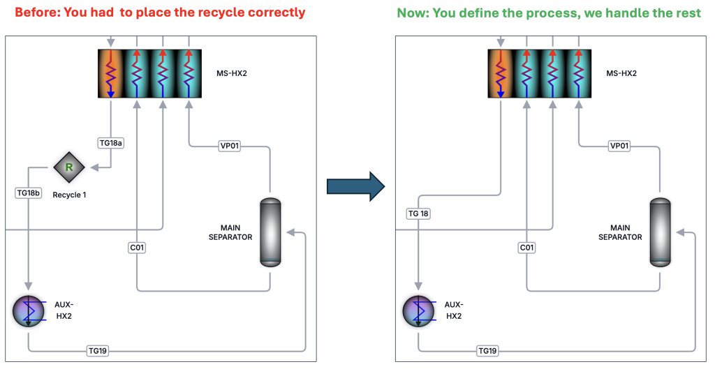
What I didn’t know was that solving such processes requires me to correctly place something called a “recycle unit”, also called just “recycle”. The recycle is the square with the green R in the illustration below. In addition to find the correct location for the recycle, I also had to provide it with realistic initial conditions and tolerance.
No matter what I tried, and no matter where I placed the recycle, the flowsheet would not converge. Then a fourth-year chemical engineering student stepped in. He had learned exactly where to place recycles for this particular process in a university course, and the simulation converged immediately. It felt like black magic to me (and still sometime does).
In a simple top-side gas processing plant, placing the recycle is manageable. In complex and integrated processes such as the CO2 liquefaction process shown below, it is a much more challenging job. To be honest, I struggled several hours to find the right location for the recycle to make the flowsheet converge and at first, I didn’t even know whether I should use one or two recycles.
Managing recycle units is arguably the main reason why setting up advanced process simulations is still a specialist job, and why entire university courses are dedicated to solving these problems. But does it need to be this way?
The recycle unit does not exist in real process plants
Here is the truth: there is no such thing as a recycle unit in a real process plant.
Recycle units exist only in process simulation software. They are not physical equipment, but artifacts of old numerical algorithms. When the first commercial process simulators were developed 40 years ago based on sequential-modular solvers, it made sense to outsource part of the numerical problem to the user. An un-converged simulation was unacceptable (and still is), and manual control improved robustness. But that historical compromise has become a burden.
Ideally, engineers should specify what the process is and how to improve it, not how the numerical solver should solve it.
Recycle units are now optional
In TP-Process, recycle units are now optional.
For users who want full manual control, recycle units remain available. You can place them anywhere in a loop and manage convergence exactly as you are used to.
For everyone else, the process is fully specified from the process flow diagram, no recycle units are required. Convergence is our responsibility, not yours.
If a process does not converge with reasonable input values, that is not a modeling failure, it is a numerical issue, and it’s our responsibility to fix it.
Turning a specialist task into actionable engineering insights
One moment that has really stayed with me was when I was watching Chief Developer in ThermoPhys Dr. Ailo Aasen explain passionately about energy efficiency to King Willem-Alexander and Queen Máxima of the Netherlands.
His enthusiasm was unmistakable and contagious. It certainly stuck with me, and perhaps with the royal family as well. And rightly so. To stay on track with global climate targets, energy efficiency must improve by around 4% per year according to IEA, more than twice the current pace.
The obvious questions are: How do we achieve this? And why haven’t we done more already?
In this article, I’ll try to shed some light on this.
What is exergy and why does it matter?
Waste heat and electricity from the socket both carry energy. Waste heat can be used to heat homes in the winter. Electricity can also provide heat, via a heater or, better, a heat pump, but it can also be used to charge your phone or power a motor.
Intuitively, we know that waste heat cannot efficiently charge a phone. But let’s imagine an imaginary process that converts the waste heat into electricity while fully respecting the laws of thermodynamics. How much electricity could we actually produce?
That is exactly the question exergy analysis answers.
Exergy measures the ability of different forms of energy to do useful work. It recognizes that electricity and low-temperature heat may contain the same amount of energy, but the energy has different abilities to perform useful work. Any serious discussion about energy efficiency in industrial processes therefore needs to be grounded in exergy, not just energy balances.
So why isn’t this the case?
Exergy analysis has been a specialist activity – until now
The short answer: because it’s painful.
Exergy analysis has not been natively supported and integrated in commercial process simulators. Engineers typically need to export stream data, extract thermodynamic properties, and then post-process everything manually in Excel or Python to calculate the exergy destruction for each unit operation.
And even that’s not the whole story. An important component of the total exergy called chemical exergy, is looked up in tables in textbooks. Yes, textbooks. In 2026.
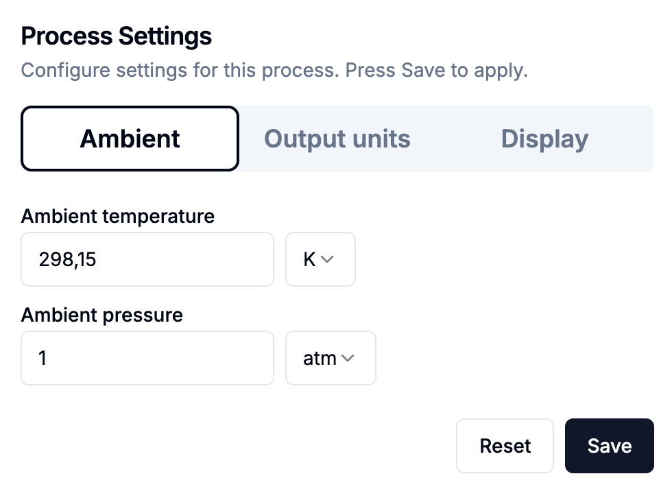
Those table values are usually defined at 25 °C. In Norway, 25 °C is a rare summer luxury. A much more realistic ambient temperature for most of the year is around 10 °C, and ambient conditions matter a lot in exergy analysis. Changing them affects all results, and therefore also the conclusions.
With today’s situation, changing the ambient temperature in exergy analysis requires going back to a handful of exergy specialists, the ones with the biggest glasses (like Ailo).
Once performed, the results are easy to interpret
Ironically, while exergy analysis is hard to perform, the results are usually straightforward to interpret.
You need an expert to do the analysis, but once it’s done, most engineers can quickly see where the real inefficiencies are and make good assessments to how the process can be improved.
Let’s look at a relevant example.
How TP-Process changes the game and makes exergy analysis easy
The equations behind exergy analysis are well defined. In principle, the entire workflow can be automated.
That is exactly what we have done in TP-Process.
Exergy analysis is now native, automatic, and available for any process simulation. No exports, no spreadsheets, no PhD required just to get the numbers.
To illustrate this, let’s look at a simplified liquid CO2 conditioning process. This is an energy-intensive system with significant potential for improvement, making it a good example.
When we solve this process and then open the results view and select Exergy, we immediately get the full breakdown of exergy destruction by unit.
The “magic” here is that all of the exergy destruction, together with the exergy added to the inlet stream, adds up exactly to the total work demand of the process. This means that if we want to reduce the work demand and thus the operating cost, we need to reduce the size of the bars representing lost work.
In this process, we notice something interesting: the heater “AUX-HX2” has a negative exergy destruction, which is physically impossible. This is a clear signal that some of our assumptions are unrealistic.
In this case it turns out that we specified a non-physical coefficient of performance (COP). After specifying a realistic efficiency for the cooler, we obtain a consistent result, and we also realize that the overall work demand increases. That’s valuable insight in itself.
Now it becomes clear that the coolers (“TG-IC1”, “TG-IC2”) are responsible for most of the lost work. As engineers, we immediately start thinking about mitigation strategies – option A, B, or C – rather than spending time calculating exergy numbers.
And if you’re working in Norway (or anywhere else), updating the ambient conditions to get a location-specific analysis is just a few clicks away.
Key takeaways
Exergy analysis is native, automatic, and integrated in TP-Process
The results are easy to interpret once they are available
Poor assumptions are immediately revealed (e.g. negative exergy destruction)
Ambient conditions can be changed easily and consistently
This functionality will help making exergy analysis a standard and frequently used part of process design, and we hope that it will contribute to improving energy efficiency at the scale required to meet climate targets.
Reactive impurities represent one of the least understood, yet potentially most critical challenges for large-scale deployment of carbon capture and storage (CCS). While CO2 purity specifications are becoming increasingly conservative, they are still not grounded in a mechanistic understanding of when, where, and why highly corrosive acids form in real CCS infrastructure.
Since 2024, supported by Gassnova, we have been developing a physics-based, mechanistic modelling engine to predict chemical reactions between trace impurities in CO2-rich mixtures. Over the past six months, we have systematically compared our model against 9394 hours of experimental data published in the last decade by the Institute of Energy Technology (IFE).
Reactive impurities in CCS must be understood before widespread deployment
CO2 captured from different industrial sources inevitably contains trace amounts of impurities at the parts per million (ppm) level. Some of these impurities are chemically reactive and can interact in ways that are not captured by conventional purity specifications.
Nitrogen dioxide (NO2) is a particularly problematic impurity that is prevalent in CO2 streams from a wide range of capture technologies. In the presence of water, NO2 forms nitric acid (HNO3), which is highly corrosive to carbon steel. If sulfur-containing species such as SO2 or H2S are also present, reactions between impurities can lead to the formation of sulfuric acid (H2SO4). If sufficient sulfuric acid forms in the gas-phase from chemical reactions, it will eventually precipitate out as an aqueous phase, which catalyzes further reactions and accelerates acid production.
For a decade, experimental work on reactive impurities has been carried out at IFE in Norway. As early as 2014, experiments conducted at Kjeller in Norway demonstrated that highly corrosive acids precipitate from CO2 mixtures containing trace impurities. Mixtures of nitric and sulfuric acid were shown to compromise the integrity of carbon steel over surprisingly short time scales of months, or even weeks. These findings underline the importance of understanding not only if acids form, but where and under what conditions they precipitate in CCS infrastructure.
Concern over acid formation is the basis for today’s extremely conservative CO2 purity specifications, such as those adopted in the Northern Lights project. In these specifications, the allowable NO2 concentration has lately been reduced to 1 ppm, which is even lower than the limit for food-grade CO2. Removing impurities to this degree is costly, and it remains unclear whether such limits are sufficient, or even necessary, to prevent acid formation under all operating conditions. For example, acids may still precipitate at even lower impurity levels if the temperature and pressure drop.
At present, uncertainty around acid formation is not just a corrosion issue. It represents one of the remaining systemic risks that can halt cost-effective CCS deployment if efficient mitigation strategies are not developed.
Why a dynamic modelling framework is needed
Acid formation in CO2 pipelines and infrastructure is governed by a complex interplay of physical and chemical mechanisms. Impurities may adsorb onto pipeline walls, where surface reactions become important. Other reactions occur in the gas phase, while solids such as sulfur or salts may precipitate under certain conditions. If an aqueous acidic phase forms, it will act as a catalyst for additional reactions, rapidly increasing acid production.
These processes are dynamic and strongly dependent on local conditions such as temperature, pressure, flow regime, mixing of streams, and transient water availability. Static impurity specifications or equilibrium-type models cannot capture these effects.
A dynamic mechanistic modelling engine is therefore essential to:
Develop effective strategies for acid mitigation and handling
Interpret and understand experimental observations
Design targeted experiments that reduce uncertainty
Predict if and where acids will precipitate in real CCS infrastructure
The Status on our modeling framework
Development of our dynamic modelling framework for reactive impurities in CO2 streams started late 2024, following discussions with the Institute of Energy Technology (IFE), which highlighted the lack of predictive tools. Since then, we have made substantial progress.
Our current framework is based on a physics-based thermodynamic description of reactive electrolyte systems, combined with state-of-the-art models for adsorption onto carbon steel surfaces. A comprehensive reaction network has been implemented, covering gas-phase, liquid-phase, and surface reactions, together with thermodynamic prediction of precipitation of relevant solid phases. Where experimental data are unavailable, reaction kinetics have been estimated using first-principles molecular methods.
The modelling engine has been extensively validated against published experimental data from IFE. Using the exact same initial and boundary conditions as in the experimental rigs, and without tuning parameters to individual experiments, the model reproduces measured outlet concentrations and dynamic behavior. The figure below illustrates this by comparing measured water concentrations at the outlet of the experimental rig (markers) with model predictions (solid line), demonstrating an excellent agreement.
In total, similar comparisons have been performed for 29 independent experiments, corresponding to 9,394 hours of operation of the experimental rig over the past ten years. For all published experiments conducted above 15 °C, the model reproduces the observed dynamic concentration profiles and predicts the onset of acid precipitation in agreement with experimental observations at IFE.
This level of agreement indicates that the modelling engine captures the dominant physical and chemical mechanisms governing reactive impurities in CO2-rich systems, at least at higher temperatures, and that it has the potential to become a predictive basis for engineering analysis rather than as a case-specific fitting tool.
From dynamic modeling framework to practical engineering tool
Experimental rigs at IFE typically use pipes with diameters on the order of a few centimeters, while real CO2 transport pipelines may be tens of times larger. In addition, experimental setups often involve continuous injection and removal of impurities, which differs fundamentally from pipeline transport or CO2 storage in tanks.
To bridge this gap, we have translated our validated mechanistic model to representations of large pipelines, tanks, and other CCS infrastructure components. A beta version of this functionality has been implemented in our software platform, allowing reactive CO2 mixtures to be propagated through pipeline networks under realistic operating conditions.
This enables identification of locations where acids may precipitate due to cooling, mixing of streams, or changes in flow conditions, effects that cannot be assessed using static specifications alone.
The way forward – reducing uncertainty
While the modelling framework has reached a level where it can reproduce existing experimental data, further work is required to reduce uncertainty in key reactions before the model can fully support high-confidence engineering decisions. The largest uncertainties are now associated with low-temperature conditions relevant for ship transport and certain storage scenarios.
Addressing these gaps requires targeted experimental campaigns combined with continued model development. This is not incremental refinement, but work that directly determines whether CCS systems must rely on conservative over-design, or can be engineered for safety and cost-efficiency based on mechanistic understanding.
Reactive impurities and acid formation remain one of the last unresolved challenges for large-scale CCS deployment. Mechanistic modelling, anchored in experimental data, is a necessary step toward overcoming this challenge and enabling CCS at the scale and cost required for meaningful climate impact.
Improving Energy Efficiency in CCS, Hydrogen and Energy systems
Student insights from the first use of our cloud-based process simulator
As part of the upcoming beta release of our cloud-based steady-state process simulator, three student groups from across Europe have used TP-Process to analyze processes central to the energy transition. Their projects covered CO2 capture by liquefaction, industrial heat pump processes and hydrogen liquefaction.
In this article, the students share what they worked on, their impressions of the software and, just as importantly, what needs improvement. Nearly half of the students had prior experience with established process simulation software, allowing for an early and honest comparison.
One key reason to use TP-Process in these projects is its native integration of total exergy calculations directly into the simulation workflow. Unlike most commercial simulators where exergy analysis requires time-consuming post-processing, TP-Process makes energy-efficiency analysis automatic, immediate and iterative.
What the students told us
TP-Process is already computationally fast, ergonomic, and easy to use
Integrated exergy analysis makes energy-efficiency evaluation fast and accessible
Collaboration through shared processes was used extensively
The checkpoint functionality makes it easy to keep track of and compare cases
Debugging and iteration felt easier and faster than in established tools
Several features (phase diagrams, checkpoints, shared use, missing process units) need refinement and improvement
From theory to practice: three technologies, one software
Despite working on very different technologies, all three groups used the same software to move from theoretical concepts to practical process insight. TP-Process allowed them to build processes, explore alternatives, and evaluate energy efficiency consistently across CCS, hydrogen, and industrial heat pump systems.
“Exergy analysis helped us go beyond energy balances and actually understand where the real inefficiencies are,” says Cecilie, who worked on CO2 capture.
“It changes how you think about process design.”
A recurring theme across all projects was speed: moving quickly from model setup to results, and spending more time understanding the process than configuring, debugging, and post-processing.
CO2 capture by liquefaction
Image from left: Cecilie Ødegaarden Gjertsen (Norway), Gabin Wantelet (France) and Emma Simone Duprat (France)
The first group analyzed a CO2 capture process based on liquefaction, a promising but energy-intensive CCS technology. Using TP-Process, they identified that the cooler and compressor train contributed most to exergy destruction and proposed innovative improvements to increase the energy efficiency.
Collaboration and workflow
The group actively used the sharing functionality to collaborate on the same process model.
“It was very ergonomic and convenient to be able to share the process,” says Emma.
“It allowed us to review and contribute to each other’s work instead of working separately.”
They noted that switching between lead user sometimes involved some delay and they encountered several bugs when using the functionality, reflecting the early-stage nature of the collaboration features.
Ease of use and calculation speed
“I don’t come from this field, and for a first attempt, TP-Process made it very easy to get started,” says Gabin.
“The interface is modern and interactive, and calculation times are very short.”
Emma highlights how quickly models could be built and accessed:
“Setting up unit operations was fast, and working directly through a web browser made the workflow smooth and efficient.”
Limitations and comparison to established tools
Some limitations became visible for more advanced setups.
“Certain components, such as strippers and adsorbers are not yet available,” notes Cecilie.
“Adding more unit operations would make advanced CO2 capture modeling easier.”
Both Emma and Cecilie had prior experience with established simulators and found the new workflow noticeably lighter.
“TP-Process requires much less setup before you can actually start working,” says Emma.
“And it’s faster and easier to debug,” adds Cecilie.
Industrial heat pump processes (CERN)
Image: Jan Bengsch (Germany)
Jan, who has previously worked in SINTEF, is now pursuing a PhD at NTNU. He worked on an industrial heat pump process related to CERN applications. His focus was on early-stage design and exergy-based prioritization.
Early design and learning
“It was easy to generate steady-state simulations quickly,” Jan explains.
“Relatively little information was required before I could start exploring cycles.”
He sees clear long-term value:
“In its current state, I can use TP-Process very well for initial heat-pump design, and I could include exergy destruction studies in my PhD.”
Areas for improvement
“The phase-diagram functionality did not work as intended for my use case,” Jan notes.
“I used a different tool for that part, but improving this would make the workflow more complete.”
Hydrogen Liquefaction
Image: Pol Estany Obiols (Spain) and Xavier Excaler Pedragosa (Spain)
Hydrogen liquefaction is highly energy-intensive, and Xavier and Pol focused on understanding where the largest losses of useful work occur. Their analysis showed that cryogenic cooling and compression dominated the exergy destruction, and they proposed improvements to the process.
Clarity and iteration
“The process representation is very clear, and implementing it is straightforward,” says Pol.
“You can get all the data you need, especially exergy and lost work, even for complex processes.”
Xavier highlights the interface:
“The drawings are intuitive, the error information is useful, and you don’t need to program anything.”
They encountered some solver-related challenges and bugs.
“When initial conditions need to be changed, it can be difficult to know which values to use,” says Xavier.
They also made extensive use of checkpoints.
“The checkpoint feature was very useful for comparing and keeping track of cases,” he adds.
“Once we understood how to use it safely, it became an important part of our workflow.”
Key takeaways from the first pilot
Across the projects, the students aligned on several points:
Fast setup and iteration allowed them to focus on understanding and improving processes
Integrated exergy analysis was a major advantage for analyzing energy efficiency
Debugging felt more transparent and easier than in established tools
Collaboration through shared models was used extensively.
Checkpoints enabled effective comparison of different cases
Some features (phase diagrams, checkpoints, missing process units, shared use) need refinement and improvement.
Looking ahead
These projects are part of the preparations for our upcoming pilot release, where 15 invited users will gain access to TP-Process starting February 1st. The students’ work demonstrates how cloud-based steady-state simulation and exergy analysis can enable fast, collaborative, and insightful process evaluation for CCS, hydrogen, and industrial energy systems.
The formation of solid CO2, commonly known as dry ice, is a critical safety concern in carbon capture and storage (CCS), as well as in LNG, cryogenic gas processing and other low-temperature applications.
When temperatures drop sufficiently, CO₂ can transition into a solid phase. This can occur directly from the gas phase at low pressures, or from the liquid phase at higher pressures. The exact conditions depend strongly on pressure, temperature and mixture composition.
Why dry ice formation is a safety risk
The formation of solid CO2 can lead to several serious operational and safety challenges:
Blockage of critical equipment, such as vent lines and pressure relief systems
Mechanical damage, if solid CO2 detaches and accelerates in the flow
Pressure surges or pipeline rupture, caused by local plugging or sudden phase changes
Because these events can develop rapidly, dry ice formation must be carefully assessed already in the design and safety analysis phase.
Typical scenarios where dry ice can form
Dry ice formation is most often triggered by rapid cooling events, for example:
Depressurization during pipeline shutdowns, ruptures or safety valve activation, where the Joule–Thomson effect causes rapid temperature drops
Loss of temperature control in storage tanks
Well operations, such as startup, shut-in or blow-out scenarios, where uncontrolled cooling may occur
In CCS injection wells, dry ice formation can lead to overpressure, loss of injectivity and potential wellhead damage.
The importance of accurate thermodynamic modeling
Predicting when solid CO2 forms is not straightforward. The formation limits depend on the full mixture composition, and accurate predictions require:
A suitable Equation of State for both fluid and solid phases
A robust phase equilibrium algorithm
Careful selection of model combinations
In a recently published study, ThermoPhys in collaboration with PhD-candidate Tage Maltby have evaluated a wide range of thermodynamic model combinations against experimental data. The results show that while some models predict dry ice formation with high accuracy, others deviate significantly and should not be used for safety-critical calculations.
From research to practical engineering tools
The most accurate model combinations identified in the study has now been incorporated as default options for dry ice predictions in TP-Cloud, ThermoPhys’ cloud-based thermodynamic software.
TP-Cloud enables engineers to:
Predict dry ice formation limits for CCS and natural gas mixtures
Quantify model uncertainty
Perform safety-relevant phase behavior calculations with confidence
The software has recently been tested by its first users, and further updates will be announced soon.
New publication
The full study has been published in Industrial & Engineering Chemistry Research and is the result of a close collaboration between ThermoPhys, PhD candidate Tage Malby, and our main research partner, NTNU.
The company ThermoPhys, founded by researchers from SINTEF and NTNU, is developing digital tools for accurate and user-friendly safety assessments in CO2 management.
ThermoPhys was established in 2024, and its first pilot project was completed in February 2025. The company currently has three employees and plans to expand. The team includes experts with more than a decade of research experience from SINTEF.
From Frustration to Solution
– We were frustrated that decades of research on CO2 and hydrogen were scattered and inaccessible to the industry, says Øivind Wilhelmsen, one of the founders of ThermoPhys. He explains that while advanced computational codes developed at SINTEF and NTNU are publicly available on GitHub, they lack user interfaces or support for the people who actually need them. ThermoPhys was founded to make this knowledge available through user-friendly software. The objective is to improve safety and reduce costs throughout the CO2 capture, transport, and storage value chain.
– In CCS, it’s not enough to know that CO2 can be stored, you must also understand how the mixture behaves under different conditions. Will it form acid? Dry ice? Hydrates? These are questions the industry is asking, and we believe ThermoPhys can help answer them, says Ernst Petter Axelsen. As Gassnova’s representative in CLIMIT, Axelsen is advisor to ThermoPhys on the project.
From Open Source Code to Commercial Interface
ThermoPhys builds on open-source research code, packaging it into a visual and user-friendly interface. – You shouldn’t have to be a domain expert to understand what’s happening inside your pipelines. But the model still has to be scientifically grounded and based on the best available data, says Wilhelmsen.
The aim is to make it easier for both operators and financial stakeholders to make well-informed decisions, based on accurate and validated calculation methods
Collaboration with Oliasoft and a Dedicated Cloud Platform
ThermoPhys is currently advancing on two fronts. In addition to developing its own software, the company is working with others who aim to offer digital CCS tools. In collaboration with Oliasoft, ThermoPhys will integrate its models into software for well injection.
“CO2 isn’t just captured, it must be injected underground. This requires highly accurate input data on the properties of CO2 mixtures with impurities. CCS is complex, and the risks are real if you don’t have control over the mixture properties. We want to make it easy to get it right the first time” Øivind Wilhelmsen at ThermoPhys AS.
At low temperatures, gaseous CO2 occupies more than 80 times the space of liquid CO2 (at the same pressure). If a pipeline, storage container or equipment has been designed for gas to form, this is likely unproblematic.
The problems arise when gas forms unexpected. This can happen because of a change of operation conditions, or due to a breach in the structure. Significant amounts of gas bubbles in the fluid can have a range of consequences on flow assurance and safety:
They can change the flow pattern, possibly leading to surges in the flow velocity because gas occupies a much larger volume than liquid.
Pockets of gas (bubbles) can form between liquid slugs and move rapidly through the equipment, leading to vibrations, noise, and potential material fatigue.
The pressure drop is likely to increase, potentially reducing pipeline efficiency if it exceeds the design specifications of the pumps.
Operating pumps at too low pressures can cause rapid formation and collapse of vapor cavities, which can erode the inner surfaces of pumps and piping. This phenomenon not only damages the pump but may also affect the connected piping and other associated equipment.
Expansion of the gas can lead to the “Joule-Thomson effect”, where the gas cools down. The gas can then cool down surrounding infrastructure, possibly leading to a loss of structural integrity in CCS injection wells.
Contact between gas pockets and liquid CO2 can lead to rapid gas condensation, which accelerates the surrounding liquid and triggers a phenomenon known as “condensation-induced water hammer”. This can result in damaging pressure surges that pose a risk to the integrity of the system.
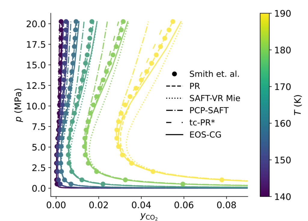
The illustration above shows the regions where liquid turns into gas for various CO2-mixtures. If the CO2 contains only 5% nitrogen, the boundary where gas forms shifts to much higher pressures (upper green dotted line) compared to pure CO2 (solid line). On the contrary, if the CO2-mixture contains 5% SO2, the pressure where gas forms shifts to lower values (upper blue dashed line).
In CCS systems, CO2 is often accompanied by impurities. When designing CCS infrastructure, it is crucial to precisely determine the composition, temperature and pressure range at which gas formation occurs. The software TPCloud will use the most accurate models and algorithms to identify this range, ensuring that appropriate safety barriers can be effectively maintained.
Morten Hammer grew up near Steinkjer in Norway. After his military service, he travelled to Trondheim, where he completed a Msc. Tech. (2000) and a PhD (2004) in Chemical Engineering at NTNU.
Morten then moved to Oslo where he worked 3 years at Fantoft Process Technologies developing a dynamic process simulator, and 4 years at SPT Group developing the tool which today is known as OLGA, a state-of-the-art software for pipeline flow assurance.
Morten moved back to Trondheim in 2011, where he has worked as a senior research scientist at SINTEF Energy Research until now. It was in SINTEF that he took the role as lead developer of the thermodynamic library called Thermopack, which was released open-source by SINTEF in 2020. Morten has, together with colleagues at SINTEF and NTNU, developed the code continuously since then.
Morten has been a visiting scientist at Imperial college in London and at the University of Stuttgart. He also works part time as an adjunct Professor at NTNU, supervising students and conducting research in the Thermodynamics group.
There are few people with more hands-on experience, knowledge and competence in thermodynamics, equations of state and algorithms for phase equilibrium calculations than Morten. He has an exceptionally broad foundation after having directly contributed to the development of software solutions, both for dynamic process simulations and transient pipeline flow, resulting in software that today is used by companies all over the world. This makes Morten a rock solid choice as Chief Technology Officer (CTO) in ThermoPhys.
As CTO in ThermoPhys, Morten Hammer will ensure that the software:
Full Stack Developer – Build software that decarbonizes the future insights from the first use of our cloud-based process simulator
At ThermoPhys, we decode the physics and chemistry behind the green transition. Our models calculate thermophysical properties—thermodynamics, chemistry, and transport phenomena—with skill that’s earned us international recognition. These aren’t just academic exercises: they ensure the safety and reliability of technical solutions for clean energy, carbon capture, and beyond. Now, we’re scaling up.
In 2025, we need a talented Full Stack Developer to turn these state-of-the-art models into robust, user-friendly tools. This isn’t just another web dev role. You’ll be our go-to expert for bridging hardcore science with scalable software—owning the stack from API design to frontend polish.
What You’ll Contribute
Python mastery – Bridge high-performance computational code with modern web stacks.
API development (OpenAPI, FastAPI) – Build the pipelines that expose complex calculations to the world.
Frontend development (React) – Design interfaces that make thermodynamics intuitive.
Databases (PostgreSQL, MySQL) – Structure data for speed and reliability.
Cloud deployment (Azure, Docker) – Containerize models for seamless scaling and absolute reproducibility in the cloud.
Why Join?
Impact: Your work accelerates clean energy, carbon capture and storage, and beyond.
Resourceful peers: Collaborate with award-winning scientists.
Ownership: Competitive salary + equity. This isn’t a cog-in-the-machine role.
Flexibility: A focus on results, not rigid schedules.
Growth: Lead web development—we’ll rely on your expertise to set the standard.
Practical info
Flexible employment: Full-time preferred, but we’ll consider part-time or summer roles for the right candidates.
My early challenges with recycle units in process simulations
My first encounter with process simulations was 20 years ago during a summer job. I was given the task to implement a model of a gas-compression train of an oil field in a commercial process simulation software. Everything went well until I encountered a stream going backwards in the process, making a “loop”.
What I didn’t know was that solving such processes requires me to correctly place something called a “recycle unit”, also called just “recycle”. The recycle is the square with the green R in the illustration below. In addition to find the correct location for the recycle, I also had to provide it with realistic initial conditions and tolerance.
No matter what I tried, and no matter where I placed the recycle, the flowsheet would not converge. Then a fourth-year chemical engineering student stepped in. He had learned exactly where to place recycles for this particular process in a university course, and the simulation converged immediately. It felt like black magic to me (and still sometime does).
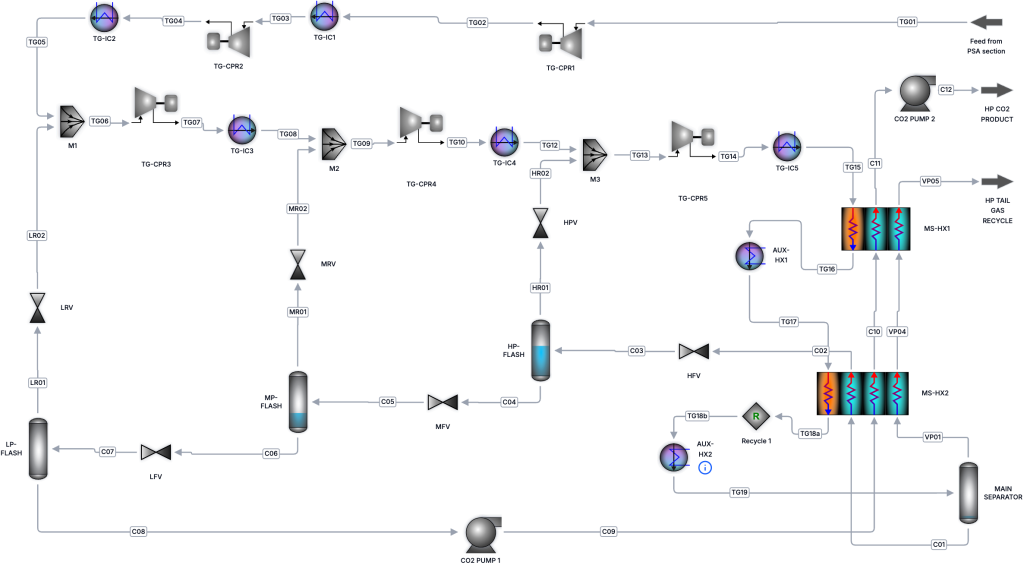
In a simple top-side gas processing plant, placing the recycle is manageable. In complex and integrated processes such as the CO2 liquefaction process shown below, it is a much more challenging job. To be honest, I struggled several hours to find the right location for the recycle to make the flowsheet converge and at first, I didn’t even know whether I should use one or two recycles.
Managing recycle units is arguably the main reason why setting up advanced process simulations is still a specialist job, and why entire university courses are dedicated to solving these problems. But does it need to be this way?
The recycle unit does not exist in real process plants
Here is the truth: there is no such thing as a recycle unit in a real process plant.
Recycle units exist only in process simulation software. They are not physical equipment, but artifacts of old numerical algorithms. When the first commercial process simulators were developed 40 years ago based on sequential-modular solvers, it made sense to outsource part of the numerical problem to the user. An un-converged simulation was unacceptable (and still is), and manual control improved robustness. But that historical compromise has become a burden.
Ideally, engineers should specify what the process is and how to improve it, not how the numerical solver should solve it.
Recycle units are now optional
In TP-Process, recycle units are now optional.
For users who want full manual control, recycle units remain available. You can place them anywhere in a loop and manage convergence exactly as you are used to.
For everyone else, the process is fully specified from the process flow diagram, no recycle units are required. Convergence is our responsibility, not yours.
If a process does not converge with reasonable input values, that is not a modeling failure, it is a numerical issue, and it’s our responsibility to fix it.
Turning a specialist task into actionable engineering insights
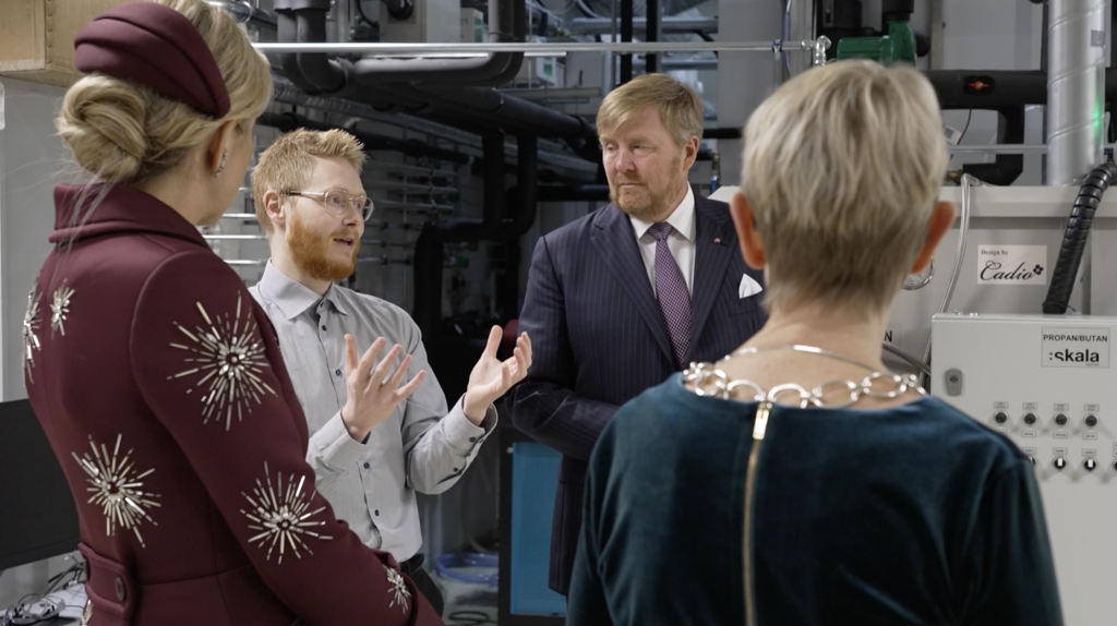
One moment that has really stayed with me was when I was watching Chief Developer in ThermoPhys Dr. Ailo Aasen explain passionately about energy efficiency to King Willem-Alexander and Queen Máxima of the Netherlands.
His enthusiasm was unmistakable and contagious. It certainly stuck with me, and perhaps with the royal family as well. And rightly so. To stay on track with global climate targets, energy efficiency must improve by around 4% per year according to IEA, more than twice the current pace.
The obvious questions are: How do we achieve this? And why haven’t we done more already?
In this article, I’ll try to shed some light on this.
What is exergy and why does it matter?
Waste heat and electricity from the socket both carry energy. Waste heat can be used to heat homes in the winter. Electricity can also provide heat, via a heater or, better, a heat pump, but it can also be used to charge your phone or power a motor.
Intuitively, we know that waste heat cannot efficiently charge a phone. But let’s imagine an imaginary process that converts the waste heat into electricity while fully respecting the laws of thermodynamics. How much electricity could we actually produce?
That is exactly the question exergy analysis answers.
Exergy measures the ability of different forms of energy to do useful work. It recognizes that electricity and low-temperature heat may contain the same amount of energy, but the energy has different abilities to perform useful work. Any serious discussion about energy efficiency in industrial processes therefore needs to be grounded in exergy, not just energy balances.
So why isn’t this the case?
Exergy analysis has been a specialist activity – until now
The short answer: because it’s painful.
Exergy analysis has not been natively supported and integrated in commercial process simulators. Engineers typically need to export stream data, extract thermodynamic properties, and then post-process everything manually in Excel or Python to calculate the exergy destruction for each unit operation.
And even that’s not the whole story. An important component of the total exergy called chemical exergy, is looked up in tables in textbooks. Yes, textbooks. In 2026.
Those table values are usually defined at 25 °C. In Norway, 25 °C is a rare summer luxury. A much more realistic ambient temperature for most of the year is around 10 °C, and ambient conditions matter a lot in exergy analysis. Changing them affects all results, and therefore also the conclusions.
With today’s situation, changing the ambient temperature in exergy analysis requires going back to a handful of exergy specialists, the ones with the biggest glasses (like Ailo).
Once performed, the results are easy to interpret
Ironically, while exergy analysis is hard to perform, the results are usually straightforward to interpret.
You need an expert to do the analysis, but once it’s done, most engineers can quickly see where the real inefficiencies are and make good assessments to how the process can be improved.
Let’s look at a relevant example.
How TP-Process changes the game and makes exergy analysis easy
The equations behind exergy analysis are well defined. In principle, the entire workflow can be automated.
That is exactly what we have done in TP-Process.
Exergy analysis is now native, automatic, and available for any process simulation. No exports, no spreadsheets, no PhD required just to get the numbers.
To illustrate this, let’s look at a simplified liquid CO2 conditioning process. This is an energy-intensive system with significant potential for improvement, making it a good example.
When we solve this process and then open the results view and select Exergy, we immediately get the full breakdown of exergy destruction by unit.
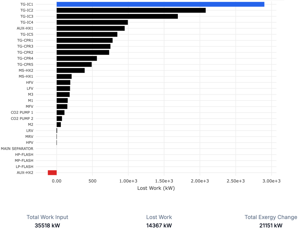
The “magic” here is that all of the exergy destruction, together with the exergy added to the inlet stream, adds up exactly to the total work demand of the process. This means that if we want to reduce the work demand and thus the operating cost, we need to reduce the size of the bars representing lost work.
In this process, we notice something interesting: the heater “AUX-HX2” has a negative exergy destruction, which is physically impossible. This is a clear signal that some of our assumptions are unrealistic.
In this case it turns out that we specified a non-physical coefficient of performance (COP). After specifying a realistic efficiency for the cooler, we obtain a consistent result, and we also realize that the overall work demand increases. That’s valuable insight in itself.
Now it becomes clear that the coolers (“TG-IC1”, “TG-IC2”) are responsible for most of the lost work. As engineers, we immediately start thinking about mitigation strategies – option A, B, or C – rather than spending time calculating exergy numbers.
And if you’re working in Norway (or anywhere else), updating the ambient conditions to get a location-specific analysis is just a few clicks away.
Key takeaways
Exergy analysis is native, automatic, and integrated in TP-Process
The results are easy to interpret once they are available
Poor assumptions are immediately revealed (e.g. negative exergy destruction)
Ambient conditions can be changed easily and consistently
This functionality will help making exergy analysis a standard and frequently used part of process design, and we hope that it will contribute to improving energy efficiency at the scale required to meet climate targets.
Reactive impurities represent one of the least understood, yet potentially most critical challenges for large-scale deployment of carbon capture and storage (CCS). While CO2 purity specifications are becoming increasingly conservative, they are still not grounded in a mechanistic understanding of when, where, and why highly corrosive acids form in real CCS infrastructure.
Since 2024, supported by Gassnova, we have been developing a physics-based, mechanistic modelling engine to predict chemical reactions between trace impurities in CO2-rich mixtures. Over the past six months, we have systematically compared our model against 9394 hours of experimental data published in the last decade by the Institute of Energy Technology (IFE).
Reactive impurities in CCS must be understood before widespread deployment
CO2 captured from different industrial sources inevitably contains trace amounts of impurities at the parts per million (ppm) level. Some of these impurities are chemically reactive and can interact in ways that are not captured by conventional purity specifications.
Nitrogen dioxide (NO2) is a particularly problematic impurity that is prevalent in CO2 streams from a wide range of capture technologies. In the presence of water, NO2 forms nitric acid (HNO3), which is highly corrosive to carbon steel. If sulfur-containing species such as SO2 or H2S are also present, reactions between impurities can lead to the formation of sulfuric acid (H2SO4). If sufficient sulfuric acid forms in the gas-phase from chemical reactions, it will eventually precipitate out as an aqueous phase, which catalyzes further reactions and accelerates acid production.
For a decade, experimental work on reactive impurities has been carried out at IFE in Norway. As early as 2014, experiments conducted at Kjeller in Norway demonstrated that highly corrosive acids precipitate from CO2 mixtures containing trace impurities. Mixtures of nitric and sulfuric acid were shown to compromise the integrity of carbon steel over surprisingly short time scales of months, or even weeks. These findings underline the importance of understanding not only if acids form, but where and under what conditions they precipitate in CCS infrastructure.
Concern over acid formation is the basis for today’s extremely conservative CO2 purity specifications, such as those adopted in the Northern Lights project. In these specifications, the allowable NO2 concentration has lately been reduced to 1 ppm, which is even lower than the limit for food-grade CO2. Removing impurities to this degree is costly, and it remains unclear whether such limits are sufficient, or even necessary, to prevent acid formation under all operating conditions. For example, acids may still precipitate at even lower impurity levels if the temperature and pressure drop.
At present, uncertainty around acid formation is not just a corrosion issue. It represents one of the remaining systemic risks that can halt cost-effective CCS deployment if efficient mitigation strategies are not developed.
Why a dynamic modelling framework is needed
Acid formation in CO2 pipelines and infrastructure is governed by a complex interplay of physical and chemical mechanisms. Impurities may adsorb onto pipeline walls, where surface reactions become important. Other reactions occur in the gas phase, while solids such as sulfur or salts may precipitate under certain conditions. If an aqueous acidic phase forms, it will act as a catalyst for additional reactions, rapidly increasing acid production.
These processes are dynamic and strongly dependent on local conditions such as temperature, pressure, flow regime, mixing of streams, and transient water availability. Static impurity specifications or equilibrium-type models cannot capture these effects.
A dynamic mechanistic modelling engine is therefore essential to:
Develop effective strategies for acid mitigation and handling
Interpret and understand experimental observations
Design targeted experiments that reduce uncertainty
Predict if and where acids will precipitate in real CCS infrastructure
The Status on our modeling framework
Development of our dynamic modelling framework for reactive impurities in CO2 streams started late 2024, following discussions with the Institute of Energy Technology (IFE), which highlighted the lack of predictive tools. Since then, we have made substantial progress.
Our current framework is based on a physics-based thermodynamic description of reactive electrolyte systems, combined with state-of-the-art models for adsorption onto carbon steel surfaces. A comprehensive reaction network has been implemented, covering gas-phase, liquid-phase, and surface reactions, together with thermodynamic prediction of precipitation of relevant solid phases. Where experimental data are unavailable, reaction kinetics have been estimated using first-principles molecular methods.
The modelling engine has been extensively validated against published experimental data from IFE. Using the exact same initial and boundary conditions as in the experimental rigs, and without tuning parameters to individual experiments, the model reproduces measured outlet concentrations and dynamic behavior. The figure below illustrates this by comparing measured water concentrations at the outlet of the experimental rig (markers) with model predictions (solid line), demonstrating an excellent agreement.
In total, similar comparisons have been performed for 29 independent experiments, corresponding to 9,394 hours of operation of the experimental rig over the past ten years. For all published experiments conducted above 15 °C, the model reproduces the observed dynamic concentration profiles and predicts the onset of acid precipitation in agreement with experimental observations at IFE.
This level of agreement indicates that the modelling engine captures the dominant physical and chemical mechanisms governing reactive impurities in CO2-rich systems, at least at higher temperatures, and that it has the potential to become a predictive basis for engineering analysis rather than as a case-specific fitting tool.
From dynamic modeling framework to practical engineering tool
Experimental rigs at IFE typically use pipes with diameters on the order of a few centimeters, while real CO2 transport pipelines may be tens of times larger. In addition, experimental setups often involve continuous injection and removal of impurities, which differs fundamentally from pipeline transport or CO2 storage in tanks.
To bridge this gap, we have translated our validated mechanistic model to representations of large pipelines, tanks, and other CCS infrastructure components. A beta version of this functionality has been implemented in our software platform, allowing reactive CO2 mixtures to be propagated through pipeline networks under realistic operating conditions.
This enables identification of locations where acids may precipitate due to cooling, mixing of streams, or changes in flow conditions, effects that cannot be assessed using static specifications alone.
The way forward – reducing uncertainty
While the modelling framework has reached a level where it can reproduce existing experimental data, further work is required to reduce uncertainty in key reactions before the model can fully support high-confidence engineering decisions. The largest uncertainties are now associated with low-temperature conditions relevant for ship transport and certain storage scenarios.
Addressing these gaps requires targeted experimental campaigns combined with continued model development. This is not incremental refinement, but work that directly determines whether CCS systems must rely on conservative over-design, or can be engineered for safety and cost-efficiency based on mechanistic understanding.
Reactive impurities and acid formation remain one of the last unresolved challenges for large-scale CCS deployment. Mechanistic modelling, anchored in experimental data, is a necessary step toward overcoming this challenge and enabling CCS at the scale and cost required for meaningful climate impact.
Improving Energy Efficiency in CCS, Hydrogen and Energy systems
Student insights from the first use of our cloud-based process simulator
As part of the upcoming beta release of our cloud-based steady-state process simulator, three student groups from across Europe have used TP-Process to analyze processes central to the energy transition. Their projects covered CO2 capture by liquefaction, industrial heat pump processes and hydrogen liquefaction.
In this article, the students share what they worked on, their impressions of the software and, just as importantly, what needs improvement. Nearly half of the students had prior experience with established process simulation software, allowing for an early and honest comparison.
One key reason to use TP-Process in these projects is its native integration of total exergy calculations directly into the simulation workflow. Unlike most commercial simulators where exergy analysis requires time-consuming post-processing, TP-Process makes energy-efficiency analysis automatic, immediate and iterative.
What the students told us
TP-Process is already computationally fast, ergonomic, and easy to use
Integrated exergy analysis makes energy-efficiency evaluation fast and accessible
Collaboration through shared processes was used extensively
The checkpoint functionality makes it easy to keep track of and compare cases
Debugging and iteration felt easier and faster than in established tools
Several features (phase diagrams, checkpoints, shared use, missing process units) need refinement and improvement
From theory to practice: three technologies, one software
Despite working on very different technologies, all three groups used the same software to move from theoretical concepts to practical process insight. TP-Process allowed them to build processes, explore alternatives, and evaluate energy efficiency consistently across CCS, hydrogen, and industrial heat pump systems.
“Exergy analysis helped us go beyond energy balances and actually understand where the real inefficiencies are,” says Cecilie, who worked on CO2 capture.
“It changes how you think about process design.”
A recurring theme across all projects was speed: moving quickly from model setup to results, and spending more time understanding the process than configuring, debugging, and post-processing.
CO2 capture by liquefaction
Image from left: Cecilie Ødegaarden Gjertsen (Norway), Gabin Wantelet (France) and Emma Simone Duprat (France)
The first group analyzed a CO2 capture process based on liquefaction, a promising but energy-intensive CCS technology. Using TP-Process, they identified that the cooler and compressor train contributed most to exergy destruction and proposed innovative improvements to increase the energy efficiency.
Collaboration and workflow
The group actively used the sharing functionality to collaborate on the same process model.
“It was very ergonomic and convenient to be able to share the process,” says Emma.
“It allowed us to review and contribute to each other’s work instead of working separately.”
They noted that switching between lead user sometimes involved some delay and they encountered several bugs when using the functionality, reflecting the early-stage nature of the collaboration features.
Ease of use and calculation speed
“I don’t come from this field, and for a first attempt, TP-Process made it very easy to get started,” says Gabin.
“The interface is modern and interactive, and calculation times are very short.”
Emma highlights how quickly models could be built and accessed:
“Setting up unit operations was fast, and working directly through a web browser made the workflow smooth and efficient.”
Limitations and comparison to established tools
Some limitations became visible for more advanced setups.
“Certain components, such as strippers and adsorbers are not yet available,” notes Cecilie.
“Adding more unit operations would make advanced CO2 capture modeling easier.”
Both Emma and Cecilie had prior experience with established simulators and found the new workflow noticeably lighter.
“TP-Process requires much less setup before you can actually start working,” says Emma.
“And it’s faster and easier to debug,” adds Cecilie.
Industrial heat pump processes (CERN)
Image: Jan Bengsch (Germany)
Jan, who has previously worked in SINTEF, is now pursuing a PhD at NTNU. He worked on an industrial heat pump process related to CERN applications. His focus was on early-stage design and exergy-based prioritization.
Early design and learning
“It was easy to generate steady-state simulations quickly,” Jan explains.
“Relatively little information was required before I could start exploring cycles.”
He sees clear long-term value:
“In its current state, I can use TP-Process very well for initial heat-pump design, and I could include exergy destruction studies in my PhD.”
Areas for improvement
“The phase-diagram functionality did not work as intended for my use case,” Jan notes.
“I used a different tool for that part, but improving this would make the workflow more complete.”
Hydrogen Liquefaction
Image: Pol Estany Obiols (Spain) and Xavier Excaler Pedragosa (Spain)
Hydrogen liquefaction is highly energy-intensive, and Xavier and Pol focused on understanding where the largest losses of useful work occur. Their analysis showed that cryogenic cooling and compression dominated the exergy destruction, and they proposed improvements to the process.
Clarity and iteration
“The process representation is very clear, and implementing it is straightforward,” says Pol.
“You can get all the data you need, especially exergy and lost work, even for complex processes.”
Xavier highlights the interface:
“The drawings are intuitive, the error information is useful, and you don’t need to program anything.”
They encountered some solver-related challenges and bugs.
“When initial conditions need to be changed, it can be difficult to know which values to use,” says Xavier.
They also made extensive use of checkpoints.
“The checkpoint feature was very useful for comparing and keeping track of cases,” he adds.
“Once we understood how to use it safely, it became an important part of our workflow.”
Key takeaways from the first pilot
Across the projects, the students aligned on several points:
Fast setup and iteration allowed them to focus on understanding and improving processes
Integrated exergy analysis was a major advantage for analyzing energy efficiency
Debugging felt more transparent and easier than in established tools
Collaboration through shared models was used extensively.
Checkpoints enabled effective comparison of different cases
Some features (phase diagrams, checkpoints, missing process units, shared use) need refinement and improvement.
Looking ahead
These projects are part of the preparations for our upcoming pilot release, where 15 invited users will gain access to TP-Process starting February 1st. The students’ work demonstrates how cloud-based steady-state simulation and exergy analysis can enable fast, collaborative, and insightful process evaluation for CCS, hydrogen, and industrial energy systems.
The formation of solid CO2, commonly known as dry ice, is a critical safety concern in carbon capture and storage (CCS), as well as in LNG, cryogenic gas processing and other low-temperature applications.
When temperatures drop sufficiently, CO₂ can transition into a solid phase. This can occur directly from the gas phase at low pressures, or from the liquid phase at higher pressures. The exact conditions depend strongly on pressure, temperature and mixture composition.
Why dry ice formation is a safety risk
The formation of solid CO2 can lead to several serious operational and safety challenges:
Blockage of critical equipment, such as vent lines and pressure relief systems
Mechanical damage, if solid CO2 detaches and accelerates in the flow
Pressure surges or pipeline rupture, caused by local plugging or sudden phase changes
Because these events can develop rapidly, dry ice formation must be carefully assessed already in the design and safety analysis phase.
Typical scenarios where dry ice can form
Dry ice formation is most often triggered by rapid cooling events, for example:
Depressurization during pipeline shutdowns, ruptures or safety valve activation, where the Joule–Thomson effect causes rapid temperature drops
Loss of temperature control in storage tanks
Well operations, such as startup, shut-in or blow-out scenarios, where uncontrolled cooling may occur
In CCS injection wells, dry ice formation can lead to overpressure, loss of injectivity and potential wellhead damage.
The importance of accurate thermodynamic modeling
Predicting when solid CO2 forms is not straightforward. The formation limits depend on the full mixture composition, and accurate predictions require:
A suitable Equation of State for both fluid and solid phases
A robust phase equilibrium algorithm
Careful selection of model combinations
In a recently published study, ThermoPhys in collaboration with PhD-candidate Tage Maltby have evaluated a wide range of thermodynamic model combinations against experimental data. The results show that while some models predict dry ice formation with high accuracy, others deviate significantly and should not be used for safety-critical calculations.
From research to practical engineering tools
The most accurate model combinations identified in the study has now been incorporated as default options for dry ice predictions in TP-Cloud, ThermoPhys’ cloud-based thermodynamic software.
TP-Cloud enables engineers to:
Predict dry ice formation limits for CCS and natural gas mixtures
Quantify model uncertainty
Perform safety-relevant phase behavior calculations with confidence
The software has recently been tested by its first users, and further updates will be announced soon.
New publication
The full study has been published in Industrial & Engineering Chemistry Research and is the result of a close collaboration between ThermoPhys, PhD candidate Tage Malby, and our main research partner, NTNU.
The company ThermoPhys, founded by researchers from SINTEF and NTNU, is developing digital tools for accurate and user-friendly safety assessments in CO2 management.
ThermoPhys was established in 2024, and its first pilot project was completed in February 2025. The company currently has three employees and plans to expand. The team includes experts with more than a decade of research experience from SINTEF.
From Frustration to Solution
– We were frustrated that decades of research on CO2 and hydrogen were scattered and inaccessible to the industry, says Øivind Wilhelmsen, one of the founders of ThermoPhys. He explains that while advanced computational codes developed at SINTEF and NTNU are publicly available on GitHub, they lack user interfaces or support for the people who actually need them. ThermoPhys was founded to make this knowledge available through user-friendly software. The objective is to improve safety and reduce costs throughout the CO2 capture, transport, and storage value chain.
– In CCS, it’s not enough to know that CO2 can be stored, you must also understand how the mixture behaves under different conditions. Will it form acid? Dry ice? Hydrates? These are questions the industry is asking, and we believe ThermoPhys can help answer them, says Ernst Petter Axelsen. As Gassnova’s representative in CLIMIT, Axelsen is advisor to ThermoPhys on the project.
From Open Source Code to Commercial Interface
ThermoPhys builds on open-source research code, packaging it into a visual and user-friendly interface. – You shouldn’t have to be a domain expert to understand what’s happening inside your pipelines. But the model still has to be scientifically grounded and based on the best available data, says Wilhelmsen.
The aim is to make it easier for both operators and financial stakeholders to make well-informed decisions, based on accurate and validated calculation methods
Collaboration with Oliasoft and a Dedicated Cloud Platform
ThermoPhys is currently advancing on two fronts. In addition to developing its own software, the company is working with others who aim to offer digital CCS tools. In collaboration with Oliasoft, ThermoPhys will integrate its models into software for well injection.
“CO2 isn’t just captured, it must be injected underground. This requires highly accurate input data on the properties of CO2 mixtures with impurities. CCS is complex, and the risks are real if you don’t have control over the mixture properties. We want to make it easy to get it right the first time” Øivind Wilhelmsen at ThermoPhys AS.
At low temperatures, gaseous CO2 occupies more than 80 times the space of liquid CO2 (at the same pressure). If a pipeline, storage container or equipment has been designed for gas to form, this is likely unproblematic.
The problems arise when gas forms unexpected. This can happen because of a change of operation conditions, or due to a breach in the structure. Significant amounts of gas bubbles in the fluid can have a range of consequences on flow assurance and safety:
They can change the flow pattern, possibly leading to surges in the flow velocity because gas occupies a much larger volume than liquid.
Pockets of gas (bubbles) can form between liquid slugs and move rapidly through the equipment, leading to vibrations, noise, and potential material fatigue.
The pressure drop is likely to increase, potentially reducing pipeline efficiency if it exceeds the design specifications of the pumps.
Operating pumps at too low pressures can cause rapid formation and collapse of vapor cavities, which can erode the inner surfaces of pumps and piping. This phenomenon not only damages the pump but may also affect the connected piping and other associated equipment.
Expansion of the gas can lead to the “Joule-Thomson effect”, where the gas cools down. The gas can then cool down surrounding infrastructure, possibly leading to a loss of structural integrity in CCS injection wells.
Contact between gas pockets and liquid CO2 can lead to rapid gas condensation, which accelerates the surrounding liquid and triggers a phenomenon known as “condensation-induced water hammer”. This can result in damaging pressure surges that pose a risk to the integrity of the system.
The illustration above shows the regions where liquid turns into gas for various CO2-mixtures. If the CO2 contains only 5% nitrogen, the boundary where gas forms shifts to much higher pressures (upper green dotted line) compared to pure CO2 (solid line). On the contrary, if the CO2-mixture contains 5% SO2, the pressure where gas forms shifts to lower values (upper blue dashed line).
In CCS systems, CO2 is often accompanied by impurities. When designing CCS infrastructure, it is crucial to precisely determine the composition, temperature and pressure range at which gas formation occurs. The software TPCloud will use the most accurate models and algorithms to identify this range, ensuring that appropriate safety barriers can be effectively maintained.
Morten Hammer grew up near Steinkjer in Norway. After his military service, he travelled to Trondheim, where he completed a Msc. Tech. (2000) and a PhD (2004) in Chemical Engineering at NTNU.
Morten then moved to Oslo where he worked 3 years at Fantoft Process Technologies developing a dynamic process simulator, and 4 years at SPT Group developing the tool which today is known as OLGA, a state-of-the-art software for pipeline flow assurance.
Morten moved back to Trondheim in 2011, where he has worked as a senior research scientist at SINTEF Energy Research until now. It was in SINTEF that he took the role as lead developer of the thermodynamic library called Thermopack, which was released open-source by SINTEF in 2020. Morten has, together with colleagues at SINTEF and NTNU, developed the code continuously since then.
Morten has been a visiting scientist at Imperial college in London and at the University of Stuttgart. He also works part time as an adjunct Professor at NTNU, supervising students and conducting research in the Thermodynamics group.
There are few people with more hands-on experience, knowledge and competence in thermodynamics, equations of state and algorithms for phase equilibrium calculations than Morten. He has an exceptionally broad foundation after having directly contributed to the development of software solutions, both for dynamic process simulations and transient pipeline flow, resulting in software that today is used by companies all over the world. This makes Morten a rock solid choice as Chief Technology Officer (CTO) in ThermoPhys.
As CTO in ThermoPhys, Morten Hammer will ensure that the software:
Full Stack Developer – Build software that decarbonizes the future insights from the first use of our cloud-based process simulator
At ThermoPhys, we decode the physics and chemistry behind the green transition. Our models calculate thermophysical properties—thermodynamics, chemistry, and transport phenomena—with skill that’s earned us international recognition. These aren’t just academic exercises: they ensure the safety and reliability of technical solutions for clean energy, carbon capture, and beyond. Now, we’re scaling up.
In 2025, we need a talented Full Stack Developer to turn these state-of-the-art models into robust, user-friendly tools. This isn’t just another web dev role. You’ll be our go-to expert for bridging hardcore science with scalable software—owning the stack from API design to frontend polish.
What You’ll Contribute
Python mastery – Bridge high-performance computational code with modern web stacks.
API development (OpenAPI, FastAPI) – Build the pipelines that expose complex calculations to the world.
Frontend development (React) – Design interfaces that make thermodynamics intuitive.
Databases (PostgreSQL, MySQL) – Structure data for speed and reliability.
Cloud deployment (Azure, Docker) – Containerize models for seamless scaling and absolute reproducibility in the cloud.
Why Join?
Impact: Your work accelerates clean energy, carbon capture and storage, and beyond.
Resourceful peers: Collaborate with award-winning scientists.
Ownership: Competitive salary + equity. This isn’t a cog-in-the-machine role.
Flexibility: A focus on results, not rigid schedules.
Growth: Lead web development—we’ll rely on your expertise to set the standard.
Practical info
Flexible employment: Full-time preferred, but we’ll consider part-time or summer roles for the right candidates.